E31 Repair Procedure 31-21 Replace Front Wheel Hub/Bearing Assembly
This repair procedure is provided “as is” and is not authoritative with respect to any BMW repair operation. Mark F. Fling is not responsible for any actual or incidental losses arising from this document’s use.
Copyright © 2005 Mark F. Fling. All Rights Reserved.
1.0 Introduction
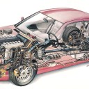
The E31 is equipped with integrated front wheel hub/bearing assemblies. Whenever the front wheel bearings fail, the entire hub must be replaced. Figure 1 shows a picture of a new hub/bearing assembly.
Figure 1 - E31 Front Hub/Bearing Assembly
The hub/bearing assembly is secured to the front stub axle with a 46 mm hex collar nut and staked into place to ensure the nut does not loosen. Once staked, the nut and bearing are covered with a grease cap. The rear of the hub is protected from road debris by a dust collar attached to the stub axle. The outer lip of this collar runs in close tolerance to a circular groove on the back of the hub assembly.
The hub also contains a ribbed pulse ring used to trigger magnetic flux reversals in the ABS transducer mounted on the stub axle carrier. The hub contains two ball bearing races to allow rotation of the hub and to absorb side thrust forces as the car turns. The hub comes pre-greased from the supplier, and the inner races are secured by a disposable plastic sleeve to ensure the hub retains the ball bearings during shipment.
Bearing failure usually occurs due to contamination of the bearing races with dirt, water, or metal shavings from the bearing itself. The bearing races may also fail by becoming out-of-round, or losing material due to a process called false brinneling. In either case, noise and vibration develop as the balls run rough over the damaged race. This vibration varies depending upon the amount of side-force developed as the wheel turns. A quick method of localizing any bearing noise as the culprit is to simply weave back and forth with the car. If the vibration varies, either one of the front hub/bearing assemblies is failing.
2.0 Tools
Since the hub collar nut is large and is retained by 225 ft/lbs of torque, some of the tools to perform this procedure will be large, and thus, expensive. Your local auto parts store may have some of the following tools for rent:
• 46 mm hex socket (substitute a 1 13/16th socket if necessary), ¾” drive recommended
• ¾” drive 8” extension
• ¾” drive slide bar with 4 foot slide-over extension (pipe is sufficient)
• Torque wrench capable of 250 lb./ft. (½” or ¾” drive)
• Torque wrench capable of 100 ft/lbs
• 19 mm hex socket
• 10 mm hex socket
• Small cold chisel or hardened steel punch
• Sharp, wedge-edged tool such as a chisel or pick to remove grease cap
• Hammer, big
• Floor jack
• Jack Stand
Here’s a picture of the hub collar nut tools:
Figure 2 - Hub Nut Tools
These tools, with the exception of the torque wrench, are available at any Sears outlet. You should not use a “speeder bar” in place of the slide bar, due to the torque required to remove the hub nut.
3.0 Disassembly
You will be performing this procedure one wheel at a time. Loosen the wheel lug nuts and jack the car using the floor jack. Insert the jack stand underneath the jack pad on the car’s frame rail. Remove the wheel. You will now see the brake disc and caliper.
3.1 Brake
Caliper Removal To remove the brake disc, it’s necessary to completely remove the brake caliper, which is held on by two 19mm bolts accessible from behind the brake disc. Removing these bolts is difficult due to the constrained space inside the wheel well.
Figure 3 - Removing the Caliper
The caliper should be hung off the strut using a length of stout wire, making sure you relieve any strain on the brake hose. Also, you should insert a spacer between the two brake pads to prevent them from closing in on each other. The space can be anything, wood, plastic, or metal of sufficient width to maintain the disc brake spacing. This will simplify assembling the caliper back onto the brake disc.
3.2 Removing the Brake Disc
The brake disc is held on by a 7mm socket Allen hex-headed bolt that screws into the hub, retaining the disc. You’ll need to remove the bolt, whereupon the disc should simply slide off the hub. If it doesn’t, lightly tap around the periphery of the disc to loosen any rust between the disc and the hub.
3.3 Removing the Hub Nut
Now comes the tough part. First, remove the grease cap by prying it off with any sharp edged object, as shown in Figure 4. The cap is on fairly tight, and a knife edge will probably be necessary to start prying if off. Don’t worry about damaging either the cap or the hub – both will be discarded.
Figure 4 - Removing the Grease Cap
Once the cap is off, you’ll see the hub nut. Notice how the nut collar is indented into a notch in the axle in Figure 5? This is called staking, and it prevents the nut from walking off the axle threads during use. You’ll need to un-stake the collar by carefully hitting the indentation back out of the notch in the axle. This takes a lot of precisely-aimed hammering.
Figure 5 - Unstaking the Hub Nut
Now comes the really hard part – removing the hub nut. Place your 46mm socket over the nut, along with the slide bar extension, and slowly but smoothly loosen the nut. With a 4 foot lever arm, this shouldn’t require too much muscle, and the nut should release smoothly, rather than with a “crack.”
Figure 6 - Removing the Hub Nut
3.4 Removing the Hub Assembly
Once the hub nut is off, removing the hub assembly can be as simple as simply sliding the entire unit off the stub axle. Most times, however, the rear inner race stays with the axle, and sometimes can be a real chore to remove. If you have a 3-prong gear/bearing puller, then by all means, use it. Here’s a trick: Insert a short ¼” socket extension to act as the fulcrum point for your bearing puller screw, since the axle is hollow and doesn’t provide a perch for the puller screw.
If you don’t have a puller handy, simply tapping the race with a rubber or plastic mallet and “walking” the race off will usually work. If you have a torch, quick shots of heat applied directly to the race may also cause the race to expand and slide off the axle. The key attribute here is patience. Heavy hammering will damage the smooth surface of the stub axle, making installation of the new hub very difficult.
3.5 Removing the Dust Collar
Figure 7 shows the hub removed and the location of the dust collar on the stub axle. If your brake protection plates are damaged, you’ll need to remove this collar to gain access to the plate’s retaining screws located immediately behind the collar. To remove the collar, simply insert a screwdriver and carefully pry the collar off the stub axle.
Figure 7 - Removing the Dust Collar
3.6 Removing the Protection Plate
Some E31s make a “clanging” noise whenever the front suspension hits a serious bump. This is due to a cracked protection plate, the large, black metal assembly mounted to the axle assembly. The plate is held by three 10mm bolts located behind the dust collar. Simply unscrew all three bolts and remove the protection plate.
4.0 Installation
Installing the new hub assemblies is, for the most part, simply the reverse of the disassembly process. Once the axle is free of the hub, clean it with alcohol to remove any residual lubricants and greases. Carefully remove metal burrs from the ABS transducer, the thin blade jutting out to the rear of the axle. Assuming you’ve removed the dust collar and protection plate, your hub should like Figure 8 below.
Figure 8 - Stub Axle Ready to Assemble
Now is a good time to check the integrity of your ball joint boots for the tie rod, thrust arm, and control arm. Cracks in these boots will result in accelerated wear and should be replaced.
4.1 Installing the Dust Collar
If you’re replacing your protection plate, simply install the new plate onto the axle assembly and use a small dab of Loctite Blue on the three retaining bolts. Torque the bolts to 10 Nm.
The dust collar is a “press fit” onto the stub axle. BMW recommends installation with a special tool, but I elected to use my vast collection of PVC fittings to create a seating mandrel as shown in Figure 9. Carefully tap the dust collar onto the axle until it is seated, with the inner lip flush with the machined shoulder on the axle. It is crucial the collar is fully seated and not distorted, since the outer rim of the collar runs in a groove located in the back of the hub assembly to prevent the ingress of dirt and debris.
Figure 9 - Installing the Dust Collar
4.2 Installing the Hub
First, remove the plastic retaining sleeve that shipped with the hub assembly. In most instances, the hub should slide onto the axle. However, mine did not, so I heated the hub to 175°F in my kitchen oven for 20 minutes. This makes the inner diameter of the two races expand, allowing for a slip-on installation.
Figure 10 - Hub Ready for Nut
I would recommend this method of heating the hub prior to installation simply because if there is any interference, you will not be able to remove the hub, and must continue with the installation process by repeatedly banging on the hub to drive it to the point where you can thread the hub collar nut and drive it home by securing the nut.
4.3 Tightening the Nut
Once the hub is mounted onto the axle, you can thread the collar nut onto the axle and tighten. Again, fit the 46mm socket and extension onto the hub nut, set your torque wrench to 225 ft/lbs, and smoothly apply tightening pressure in one continuous final stroke. Do not jerk the nut onto the axle. Spin the hub. It should be slightly tight and not spin freely. This is the correct amount of preload needed for the ball bearings to seat in their races.
Figure 11 - Torqueing the Hub Nut
4.4 Staking the Hub Nut
Once the nut is secure, you stake the nut onto the axle using a cold chisel or punch to knock an indentation in the nut’s collar opposite to the notch located in the axle. When you are done, it should look like Figure 12, shown below. The stake indentation must extend into the notch to prevent the nut from loosening.
Figure 12 - Staking the Hub
4.5 Installing the Grease Cap
Prior to installing the grease cap, dab a little sealant along the lip. I use Hylomar, but any good metal-tometal sealant will work. Then carefully tap the cap into place until it is flush with the hub. The press fit is very tight, so you’ll have to work around the periphery of the cap in order to get it to seat correctly.
4.6 Install the Brake Disc
Next, lightly smear the mounting surface of the hub flange with moly disulphide anti-seize. This will prevent the brake disc from rusting onto the hub. Keep the anti-seize out of the wheel stud threads. Then mount the brake disc, line up the 7mm Allen head retaining bolt, and screw the bolt flush with the brake disc.
4.7 Install the Brake Caliper
Remove the brake caliper from its hanger bracket. Remove any spacers between the pads and quickly wedge the caliper back onto the brake disc. Coat both caliper bolts with a dab of Loctite Blue and secure with 84 ft/lbs of torque.