The LED THREAD for Exterior and Interior lighting

  • Zitat von Paul_M;52103

    Nice job. The main one that annoys me is the ASC button, it's much duller than the others. I was going to try replacing the bulb/LED but couldn't work out how to open it without destroying the switch.


    I just received my spare button... I tried to cut the tabs smaller and smaller until I could remove the printed circuit board (PCB), but that didn't work. The holes are too small to leave enough plastic to create new melted tabs. So I just cut 'em off. Here's what the internals look like:


    Before opening the button I was afraid all force generated by pressing the button would come on the PCB inside the button and thus also on the plastic tabs. But that's not the case! The part of the button you press on is fixed in the top half of the enclosure. Even with the PCB out you cannot press it beyond a certain point. Underneath this part is a small rubber rod that presses the actual switch on the PCB. In other words, no matter how hard you press on the button, very little force will make it to the PCB. A few dabs of hot glue are probably enough to keep it seated. If you want to be certain, make a few spacers that sit between the PCB and blue button base. It will be even stronger than the original.

    The button internals reveal not one but two filament bulbs. One is obviously to illuminate the ASC lettering and should be replaced with LEDs. The other one should illuminate the button when ASC is active, but as far as I know that feature is not enabled in the E31 (it's shown on the dash instead). So replacing the second bulb with a LED is not necessary.

  • Knowing what to expect I finally dared to open my own ASC button. I didn't waste my time by trying to recover the melted tabs. I just turned the tab heads with a pair of long nose pliers until they came of - a clean cut. I will fixate the PCB later on with a dab of hot glue and some spacers. The spacers must be exactly 8mm tall.

    Apparantly my button is a different revision. Where the other ASC button had four melted plastic tabs, this one had six. Don't break off the two smaller tabs - they don't hold the PCB!


    As you can see the inside is slightly different. This one has a plastic bulb holder and only one filament bulb - that might explain why the ASC light never comes on in an E31.

    Mounting a pair of LEDs will be done in similar fashion as the EML button. I'll post a picture when ready.

    Update: Apparantly the spare ASC button I got and opened first, is from an E32. It suddenly struck me the connector is different. A closer look also revealed a different part number... Sorry, bad research from my end. The one in this post is the true and correct E31 ASC button.

  • And here's the modified ASC button. Sorry for the bad picture (depth-of-field way too small). I hadn't noticed the camera's aperture was set wrong until I had the button completely assembled again. Dammit :)


    I determined the optimal resistance to be 10k (10000 ohm). Note there's already a 130 ohm resistor in the button's base. I didn't bother taking that one out, but put the new 5k6 resistor in series with it.

    The two black rectangles you can see on the picture above are the spacers that will be put between the two circuit boards and which will replaced the melted tabs. They are exactly 8mm (0.315") tall and around 15mm (0.6") wide. Thickness is 1mm (0.034"). Just put the bottom PCB (the actual switch) back into the button enclosure. Make sure it sits in correct position, then glue the spacers to the enclosure sides - one on each side - and put the button base back in place. Solid as a rock!

    I can't post pictures from the buttons in action yet as I still have the center console out, but on my test bench they all look equally bright. Looks very nice :)


  • Hello revtor:

    I find it very interesting to your document at the club in spain, we are several problems with the lights of the climate, I would like to put this document in the forum of e31.es, if you allow me put it, but would prefer to be on your that we published in our pages.

    A greeting

    Presidente del Club BMW Serie 8-Spain (e31.es)
    Chus.

  • Zitat von chusher;55138

    I find it very interesting to your document at the club in spain, we are several problems with the lights of the climate, I would like to put this document in the forum of e31.es, if you allow me put it, but would prefer to be on your that we published in our pages.

    Sure, no problem! You may post the article at your forum! :cool:


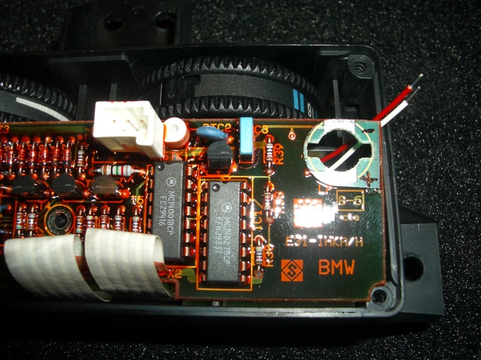
    Here's a link to the full article: HVAC/IHKA controller roller wheel illumination mod (@Bimmerforums.com).

  • Zitat von revtor;55142

    Sure, no problem! You may post the article at your forum! :cool:


    Here's a link to the full article: HVAC/IHKA controller roller wheel illumination mod (@Bimmerforums.com).


    :top: Revtor thank you very much, right now I have hung in the forum of the Spanish Club page that you have given me.
    Could make a visit to that forum because we are starting already and you know the beginnings are hard and your experience would help us.


    http://www.e31.es/foro/index.php

    Presidente del Club BMW Serie 8-Spain (e31.es)
    Chus.

  • Zitat von TallTony;44938


    I then placed the 3 LEDs in the hole by each of the dials. Forgot to take pictures at this point, but I secured the LEDs with a dab of hot glue, and then wired them in parallel to the dash bulb source so they each receive the same amount of current.


    :lol: :lol:


    Tony & Wayne on the photo above it shows the positive on the top part of the connection and the negative at the bottom is this right:hmmmm:
    Sorry to sound thick but I have the unit in front of me with the LED's mounted in position etc and only need to solder the connection together but the car is 100+miles away to check this out with a multimeter which is also at home:banghead:
    I just wanted to finish the unit tomorrow. Thanks fella's:top:

    :driving2:Its been a year since I sold her and I still miss her.......


    Lloyd

  • You are correct, Lloyd. Here's another picture that shows the connections. The red wire is the positive lead, the black one the negative lead. The connections are made on the bottom side in this example. This way the leads and solder joints cannot be seen when the unit is assemled.


    Or Martin's picture where he indicated + and - on the PCB:

  • Right the HVAC unit is back in and lights up a dream. However the computer now does not work i.e. it does not light up at all not even the clock:banghead: Any idea's friends I thought it might be a fuse number 31 in the boot:hmmmm: Or am I looking in the wrong place? :hmmmm: It still bong's with or without it connected?

    :driving2:Its been a year since I sold her and I still miss her.......


    Lloyd

  • Hi Tony, I've read your led mods with interest and wondered if you could point me in the right direction to replace the map lights ?

    Cheers
    Alex

    There are 10 types of people in this world,
    those who understand binary code,
    and those who don't !

  • To date I haven't done the map lights, although I do have a plan for them. I've got some free time coming up and I plan to post what I did with pictures.


    Been about 12 months now since I did the lights, and most of them are still holding up ok. The door sill illunimators have been the only issue, with a bit of flickering, but after replacing the festoons they are back to normal too.

  • Sidelights


    Hi Tony, I followed your instructions for replacing the sidelights with led's, I got 36 led bulbs which work fine, but despite being white, have a blueish tinge unlike your super bright white ones. I get sidelight failure bong about every 3rd startup. Are yours the 45 led ones ? do you have an ebay link to them ?

    Cheers, Alex

    There are 10 types of people in this world,
    those who understand binary code,
    and those who don't !

  • It's been 6 months since my last update in this thread and I still haven't made any progress on any field... I haven't put the center console in my car yet, but I finally took the time to make a picture of the center console buttons with modified illumination.

    I think most of us have already noticed the illumination of the buttons on the center console isn't exactly coherent. If you check some of my previous posts in this thread you can see I modified the buttons to have a better matching illumination. Here's the result:


    Perhaps the modified buttons (seat heating is as reference) are a slight tad too bright, but the picture with long exposure time exaggerates the difference. I didn't notice until seeing the picture. Most important is that all buttons now have exactly the same color and virtually the same brightness. Another minor annoyance fixed :mrgreen:.

  • Thanks Tony, I bought the bulbs recommended by David8, superb ......but consistent 'bongs'......I'm using the resistor mod as per your bulbs....do I need different resistors with theses bulbs ?

    :drink1:
    Alex

    There are 10 types of people in this world,
    those who understand binary code,
    and those who don't !

  • the nights are drawing in and it is the time of year to start thinking about lighting again :laugh:

    How about these H1 LEDs for FTP Flashers, Pop Up Fogs.....


    With them being SMD type LEDs I would assume they are pretty bright. Proabably not as much as standard, and I wouldnt go fitting them in MAIN BEAM or anything, but might be worth a punt to see if they look OK along side the HID beam which is 6000K....

    what this space...

    :cool::toothbrush::cool:

Jetzt mitmachen!

Sie haben noch kein Benutzerkonto auf unserer Seite? Registrieren Sie sich kostenlos und nehmen Sie an unserer Community teil!